
Automated bathtub using Raspberry pi
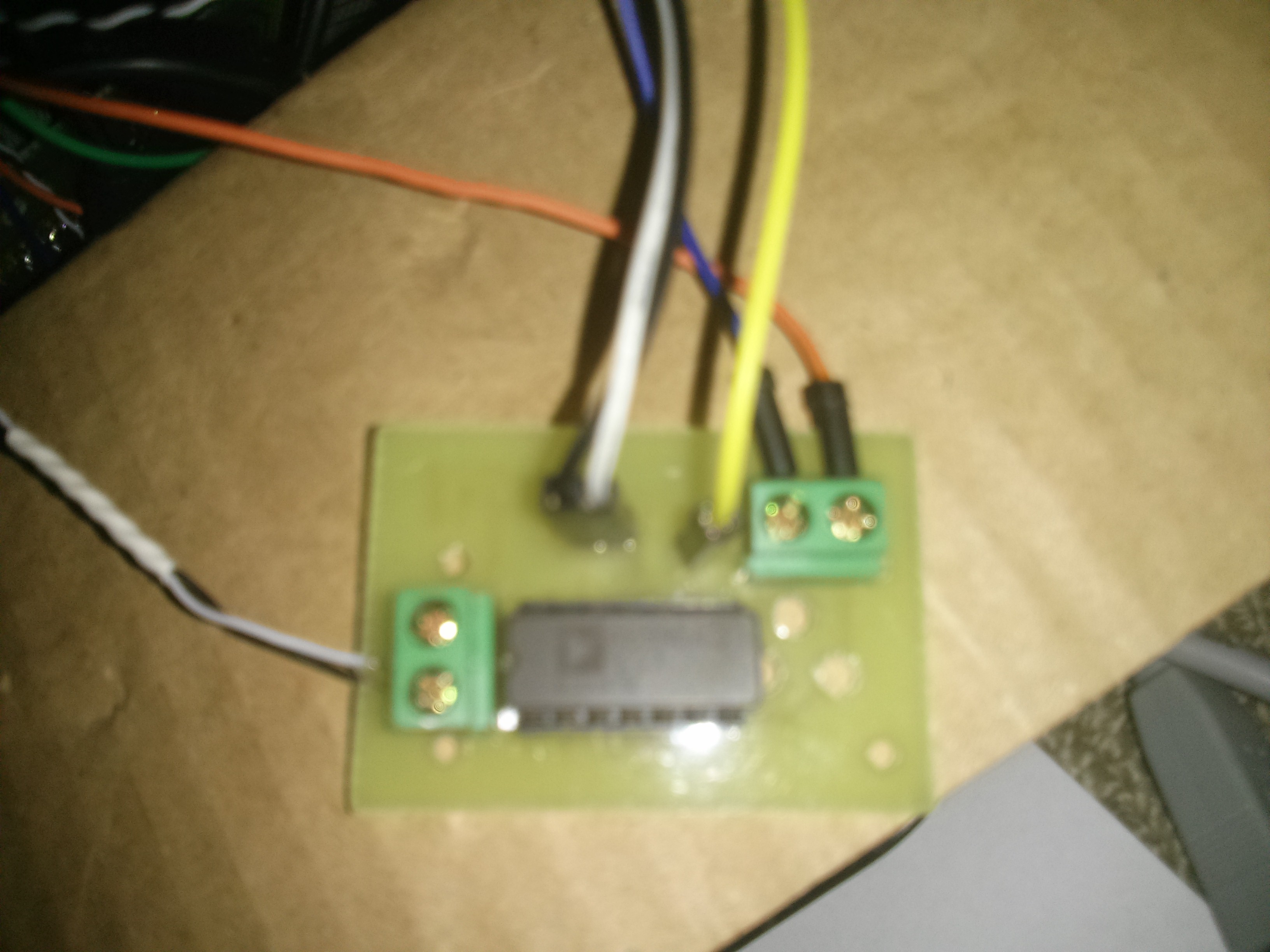
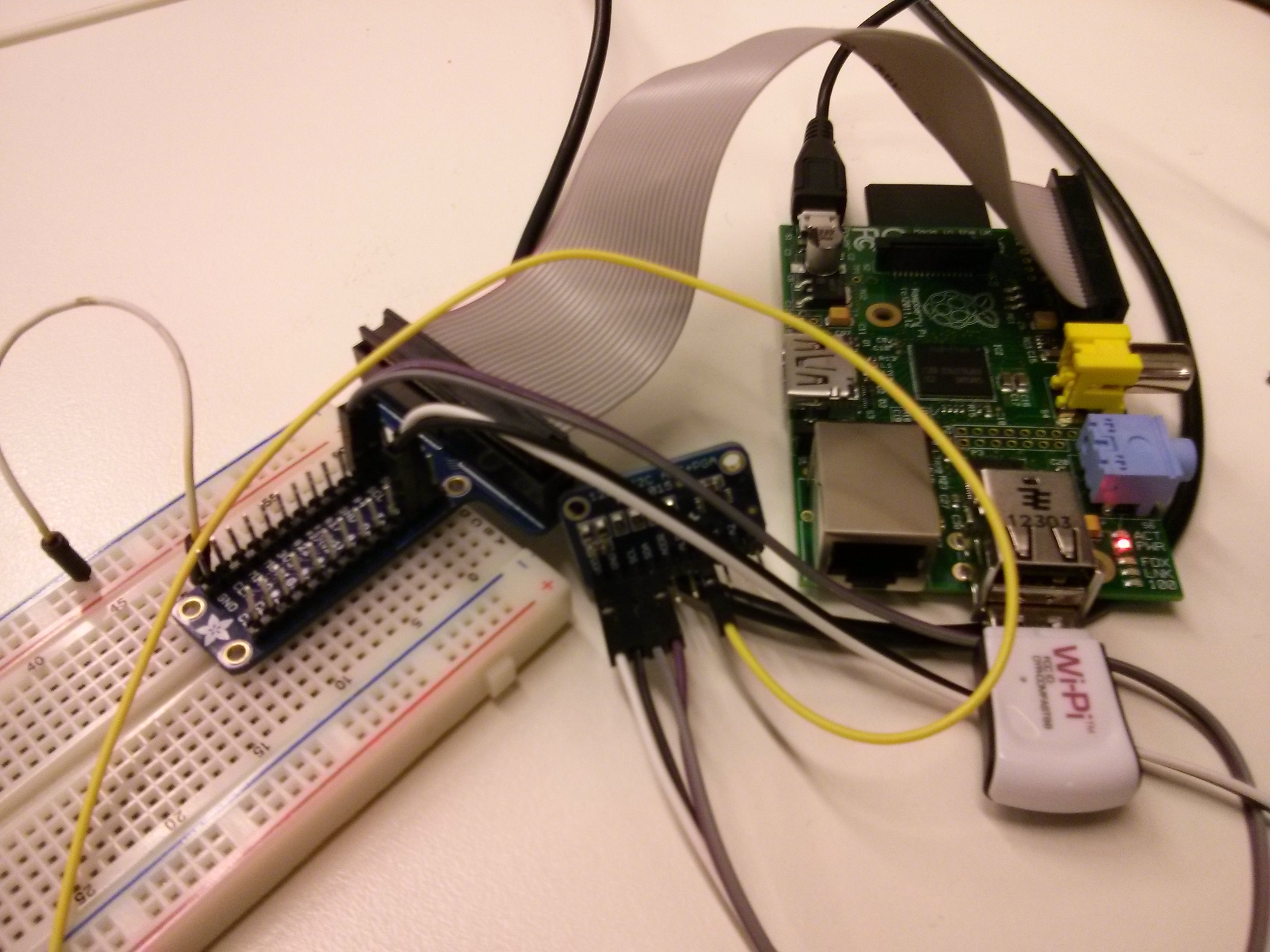 Breadboard testing components of the Automatic bath
As it is the end of semester I thought I should write a post about my 3rd year design project that I undertook with a randomly selected team of myself and five others.
The idea was to design and implement a prototype of an automated bath that would be able to be remotely controlled via a mobile device such as phones and tablets. We set out to be able to control the depth of the water as well as the temperature. The other main feature we set out to achieve was to make the bath compatible with the existing open home automation standard KNX as the project was meant to be industry supervised.
Having taken a whole semester of our year long project to be even given access to the KNX equipment supplied by the university we made the decision to drop that component of the project and focus solely on making an automated bathtub and the associated remote control system.
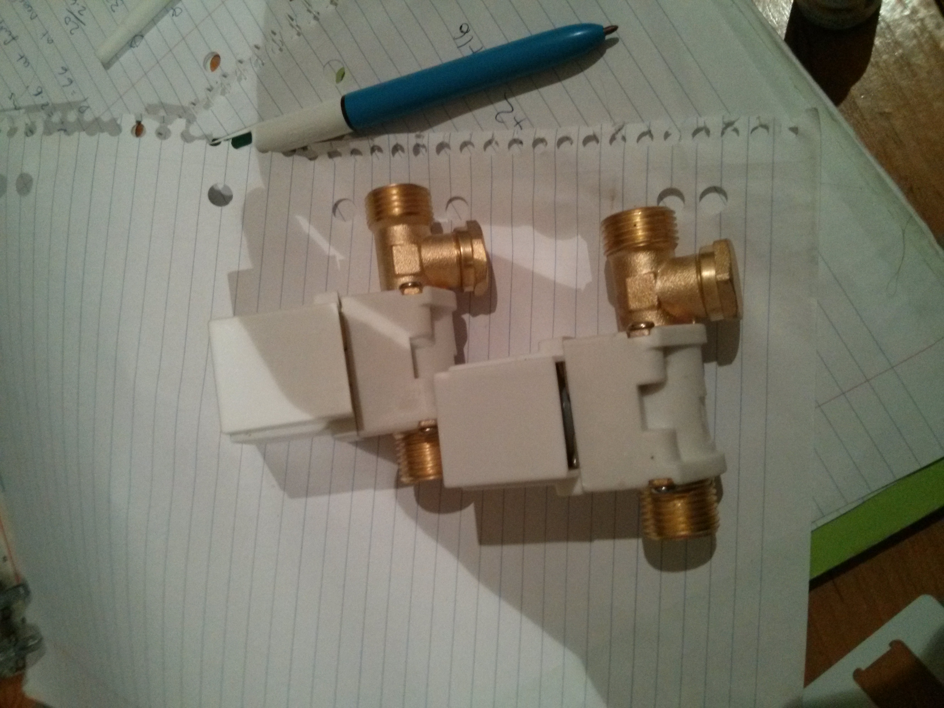
Controlling the bath taps & plug
In order to control the hot and cold taps we found many solenoid valves online all ranging in voltages, maximum temperatures as well as being normally open/closed. We selected a normally closed solenoid valve that operates on 240VAC and a maximum temperature of 75°C. Using a relay circuit we are able to switch on/off the 240V and therefore control the hot and cold taps.
For the plug we chose to use a 5V Impulse solenoid, which operates in such a way that it changes it’s open or closed state when a voltage pulse of opposite sign to the previous pulse. Simply put to change from open to closed we would apply a +5V pulse and then to open the valve again we would apply a -5V pulse. This is quite good for our application as it means that if the power were to go out whilst the user is in the bath they would be able to continue and the bath could be drained after the power comes back on.
In hindsight I think from a safety perspective it would not be wise to even suggest using 240VAC devices right near water and it would be better to use 12VDC or other solenoid valves.
Controlling the Relays/Solenoid valves
As the raspberry pi cannot supply much current it was important that we used a BJT configuration and a separate power supply to power the relays. From this we were able to control the 240v supply and in turn control the hot/cold tap solenoid valves. Using python and the RPi.GPIO library we were able to switch our relays on a breadboard. From here we started drafting a custom pcb to house the relays and BJT configuration for easy connection to our raspberry pi using a GPIO ribbon cable.

For the plug solenoid we needed a different configuration as we needed to be able to supply +5v and -5v from the same pcb. We employed the following circuit which basically used one GPIO pin on the raspberry pi to switch the voltage polarity and one to turn on the voltage. In the software component we were able to switch the voltage and then enable it for a short period of time to send the “pulse” that is required for the impulse solenoid to switch.
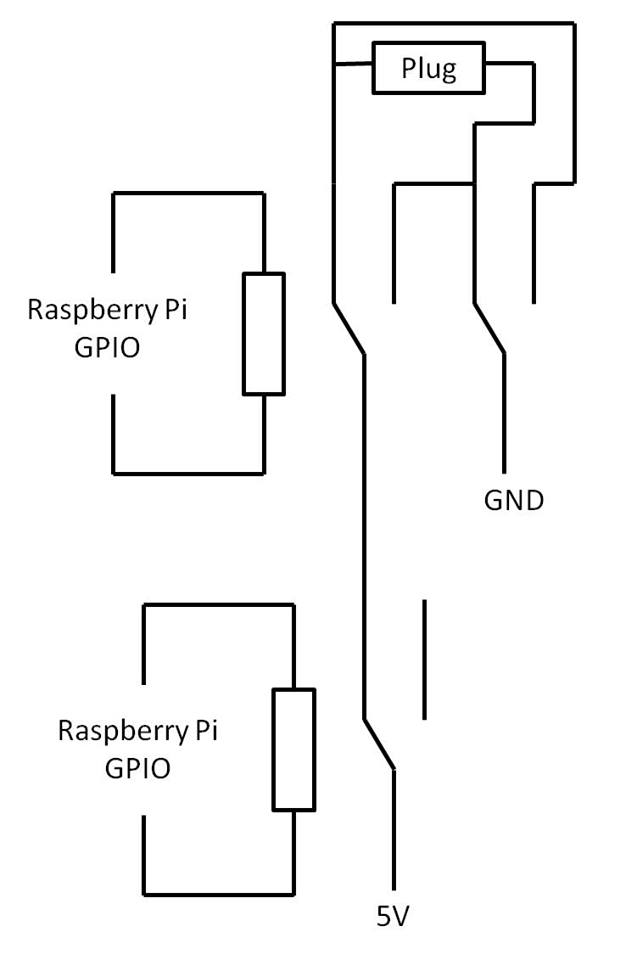
For this circuit we used on SPDT relay and one DPDT Relay.
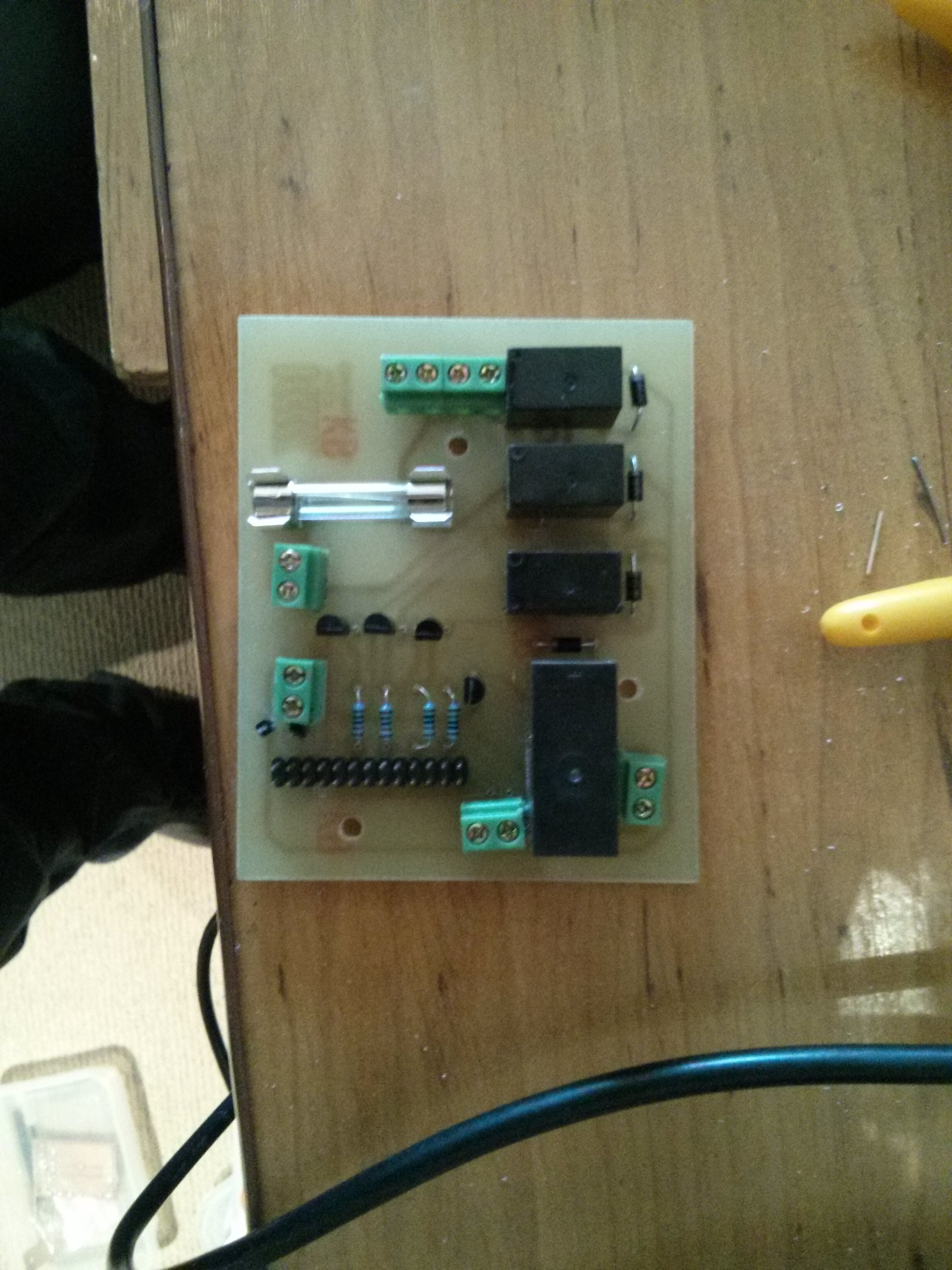
Custom PCB
Temperature and depth reading
For reading the depth of the bath we chose to use a liquid level sensor produced by milone and supplied by little bird electronics (Australian sparkfun distributor). The level sensor consists of a length of plastic “etape” that changes resistance dependent upon the water level. Using a simple voltage divider circuit this variation in resistance can be measured into an analog voltage and then read by a microcontroller. The main downside to this is that the level sensor needs to be in the liquid.
For temperature recording we chose to use a J type thermocouple from RS components. This was selected as it operates well within our required temperature range. Being pressured for time and also being a bit inexperienced in electronics we didn’t initially realise that we would need a thermocouple amplifier to amplify the minuscule voltage that the thermocouple generates. We settled upon the AD595-AQ thermocouple amplifier as we did not have time to mess around and build an amplifier circuit from scratch. This worked perfectly and also had a built in celcius thermometer test circuit which was useful for testing the chip.
Web server component
We initially thought that the majority of what we needed to do could be achieved by using an arduino microcontoller. An arduino has plenty of digital IO pins as well as plenty of analog pins, we decided against this because we wanted to host a web server of some description to control our bath using Wi-Fi. We settled upon the Raspberry pi as it has GPIO pins that can control digital devices and it is more than capable of hosting as small server to display our web application.
The downside of using a raspberry pi is that it cannot read analog voltages like that which we would need for reading the bath temperature or depth, for this purpose we chose to use an ADS1015 Analog to Digital converter sourced from Adafruit. Using the Adafruit python library we were able to read analog voltages from the level sensor and thermocouple temperature sensor.
Being able to read the values using python as well as switch the GPIO pins for the solenoid control we needed a graphical user interface and web page. For our project I hacked together a simple twitter bootstrap responsive layout and one of the other guys built the php backend which was using system calls and piping the input back into the server, this seems to be less than ideal and is something I will address if I come back to this project.
Conclusion
Throughout the design process we ran into plenty of setbacks including many of the joys of working together with less than motivated group members and parts damage. The day of our final demonstration our analog to digital converter blew and we were not able to demonstrate our project. This was a great project and I learned a great deal however there were many aspects I felt to be a bit underdone or incomplete and I would love to spend some of my holiday time completing this project properly.
If I get time here is a list of the things I would like to fix:
- Software implementation into an all python framework such as django or bottle.py
- Investigation as to whether a N/O solenoid might be better instead of an impulse solenoid for the plug
- Fully test and potentially implement this system into someone’s home.
- Refine some of the design decisions
- Investigate whether a contactless liquid level sensor might be viable